This article aims to explain the circle diagram and its application for synchronous reluctance machines (SynRM). The general steady state voltage equation for the machine in the dq reference frame was derived in this article, as:


Expressing the flux linkage in terms of current and inductance, (i.e.  and
and  ), gives:


The torque can be calculated by using the conservation of energy principle, expressed as Torque  Speed = Voltage Current, or more specifically,
  . By substituting the voltage equations (in terms of current and inductance) into the energy conservation equation, we get:

Readers should be aware that the equations for  ,
,  and
and  are in the per-unit system. For further details, refer to the associated article. Also,
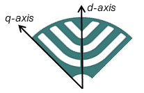
  , defined based on the dq axes in the figure below, is considered the most inductive (low magnetic reluctance) axis. This aligns with the definition used in interior permanent magnet (IPM) machines, where the d-axis corresponds to the direction of the north pole magnetization when permanent magnets are placed in the flux barrier regions (the white areas in the figure). Alternatively, the d-axis can be the most inductive axis, resulting in slightly different equations; however, this discussion is beyond our current scope.
From the photo above and considering different inductive paths of d and q axes, it is evident that is larger than  . Assuming fixed inductance values, we can define a saliency ratio of
  , so,
, so,  . Generally, this ratio is not constant and can vary due to saturation and cross-coupling effects, which are ignored here for the sake of simplicity.
The voltage and current limits are the rated voltage and current of the motor drive which can be expressed as below in a per-unit system


To express the voltage limit equation in terms of  and
and  , we substitute and with their respective inductance and current values. Consequently, we obtain:

This represents the equation of an ellipse centered at the origin of the dq coordinate system, with its ellipticity depends on and values. The ellipse equation can be rewritten in terms of the saliency ratio as:

The final element for voltage and current diagram is the torque equation. It’s beneficial to rewrite the torque equation in terms of saliency ratio, current value and angle instead of its dq components. Given that  and
and  , where
  is the phase advance angle, using the trigonometric identity
  we can rewrite the torque equation as:

According to the above equation, maximum torque occurs at  , when the current is unity, equal to rated current. Note that this is based on the assumption that we have ignored saturation, cross coupling, and losses.
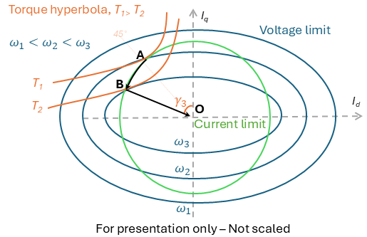
At low speeds up to the rated speed, the voltage ellipse is large enough to completely enclose the current limit circle. Consequently, the only constraint is the current, which can be set to its rated value at a 45-degree angle, providing the rated torque,  . This region, extending from zero to rated speed,
  in above diagram, is known as the constant torque region. Point A in the circle diagram indicates the set current. At this point, the unit current circle is tangent to the unit torque hyperbola (rated torque) and intersects with the voltage limit ellipse at the base speed of .
At speeds exceeding the base speed, the operating point moves along the current limit curve AB at the intersection of current circle and voltage ellipse. In this region, flux weakening region, the current angle is controlled to be within voltage limit. As the operating point moves along curve AB, torque decreases (since the angle isn’t at its optimal 45 degrees), but power might increase due to the speed rising faster than the torque decreases.
At speeds just above  , the voltage constraint causes the current to decrease from its unity value. The torque hyperbola becomes tangent to the voltage limit at any speed above along line OB, maintaining a constant angle of
  . Both torque and power decline with increasing speed. At a certain speed, called the maximum speed, the torque generated is only sufficient to counteract the internal frictional torque (with no load). Beyond this speed, the frictional load surpasses the torque generated by the motor.